
External Author – Sam Quick
Note that this tutorial is not my own work, but was developed by the speedy Sam Quick and is hosted here for convenience.
General
Carbon fiber is a common material in the aerospace industry, owing to its strength and other properties as a composite material. It is lighter than aluminum and can be molded into relatively complex shapes. It is commonly used as spars and aerodynamic shells. However, the process of creating a carbon fiber part is quite complex and time demanding. Carbon fiber is also quite expensive, so there are many factors that should be weighed before devoting time, money, and material to a part.
Before beginning, be aware that carbon fiber layup requires close contact with dangerous and unpleasant chemicals. Always wear gloves when handling raw carbon fabric, uncured resin, or hardener, and when doing processing for the final part. Wear an N95 mask or a respirator when working with resin or processing carbon parts. Carbon fiber dust is a carcinogen and inhalation or contact with skin should be avoided.
This guide is not definitive, and it is only intended for hobby/club use. This guide will detail the process of a wet layup for carbon fiber parts with a room-temperature cure in a vacuum bag. There are other methods of making carbon fiber parts, but they are outside the scope of what the DBF club has access to at the time of writing.
Materials
- Carbon fiber fabric
- Disposable gloves
- Mask or respirator
- Mold base
- Plastic sheeting
- Vacuum bag material
- Bag tape
- Plastic tape
- Breather fabric
- Vacuum puck
- Vacuum pump w/gauge assembly
- Scale
- Isopropanol
- Mixing cups for resin
- Popsicle sticks
- Release film
- White rags/paper towels
- Bucket with water
Step 1 – Preparing the Molds
The mold is one of the most critical parts of a successful layup. When designing a mold, the main considerations are material, shape, and type. The material must be rigid enough that it will not deform under pressure, so materials such as wood, metal, or 3D-printed plastic are suitable options. The finish of the mold should be as smooth as possible to avoid resin buildup and produce a nice surface finish on the carbon fiber part. The shape of the mold should consider the shape of the intended part and the compression type that will be used for the cure. Some parts can be clamped in a single direction while curing, which bypasses the need for a vacuum bag. However, any part with curvature or complexity will generally need to be cured under a vacuum. Carbon fiber plys can be very thin, so if a mold consists of positive and negative parts be sure to give some allowance to the ply thickness. As a general guide, consider one ply to be approximately 0.009” thick, but this will vary depending on the fabric and the amount of resin used. If a clamped, compression mold is desired, be sure to design the mold such that it is possible to apply clamps to produce uniform compression across the entire part. A final consideration is for the demold process. Once the part has finished curing, it will need to be separated from the mold. This can be assisted with physical and chemical barriers between the part and mold, but the shape of the mold is an important factor when demolding a part. Design the mold such that the geometries can be separated easily (avoid overhangs, corners 90° or greater, and fully encapsulated molds or parts).
Once the mold is designed and fabricated, there are some additional steps to ensure a good part and easy demold. The first of these is to have a physical barrier between the mold and the part. This has been accomplished previously by using plastic packing tape over the mold surface. More specifically, the tape found at the following link tends to provide a good barrier, be non-reactive with mold release, and encourage mold reuse (https://www.uline.com/Product/). Be sure to apply the tape to the entire surface of the mold, as the resin will squeeze out and get everywhere during the compression and curing processes. The next step is to clean the mold. This ensures that there is no dust, dirt, or debris that will find its way into the part and cause weak spots. To clean the mold, wet a disposable rag with isopropyl alcohol and run it across the mold surface. Try to clean in a single direction, so that the dirty rag never touches any parts that have been cleaned already. Once the rag is dirty, dispose of it and repeat the process until no more dirt comes off. This can take a few rags for a small part, or even dozens for large surfaces, so it is important to make sure that the mold is completely clean. The final step of mold preparation is to apply mold release. To do this, apply a generous amount of FibreGlast 1153 FibRelease to a rag and apply it to the entire mold surface. Note that the mold release is not safe to handle with bare skin. Wear nitrile gloves when using mold release. Typically release only needs to be applied to the layup surface (the part that will actually be in contact with the fabric), but due to the expected amount of overflow and resin bleeding cover the entire surface to help the demold process. The mold release takes about 5 minutes to flash off, at which point another coat can be applied. Apply 3-4 coats of release over the entire surface of the mold to make sure there is good coverage.
Step 2 – Preparing the Carbon
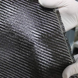
When rolling out the carbon fabric, be sure to cut on a clean surface. Also be sure not to cut directly on the surface of a table – use some sort of cutting surface. Notice that the raw carbon fabric has fibers creating a weave, as shown in Figure 1. The direction the plys are cut is based on this weave pattern: if the cuts are running parallel with the fibers, it is a 0/90° cut (since the angle between the cut and the fibers are 0° and 90°). If the cut is made at an angle to the fibers, it is named by the angle of the cut (so a ±45° cut runs at a 45° angle to the fibers). The fibers also show what directions the carbon parts will be strongest, since applied forces will tend to move along the fibers. Because of this, it is possible to create parts that are extremely strong in one direction, but not very strong in others.
The size and shape of carbon fiber plys vary widely depending on the part. Generally, plys will be roughly rectangular as the wet layup process allows the fabric to be molded, trimmed, and layered. For some parts, however, the plys will need relief cuts to allow them to fold onto themselves without wrinkling. Relief cuts are common for corners and other large 3D angle changes. When cutting and placing plys, try to ensure the weave stays consistent. If the weave of the fabric gets distorted, it can create weak spots in the part or even holes if the part is only one ply thick.
Be sure to use a straightedge when making the cuts to ensure consistent ply sizing. The raw carbon fabric can be cut with a normal razor blade, and the cuts are much easier to make when there are multiple people available to help hold the weave in place. The raw carbon fabric is a skin irritant, so wearing nitrile gloves is recommended. In addition, the fibers can puncture the skin and leave nearly invisible splinters that are difficult to remove, so long sleeves are also advised.
In addition to carbon plys, at this stage it is necessary to cut plastic sheets to help spread the resin. Each ply will need to be sandwiched between two sheets of plastic for resin saturation, so cut plastic sheets that are oversized to prevent resin from leaking out the sides. Approximately an inch margin around the carbon ply will be sufficient. These sheets can be reused in the same layup, so if there are many large identical plys each one does not need its own pair of sheets. Note that the sheets can only be used during the same layup – if there is cured resin on the sheets it could get stuck in the part and create weak points.
Step 3 – Preparing the Resin
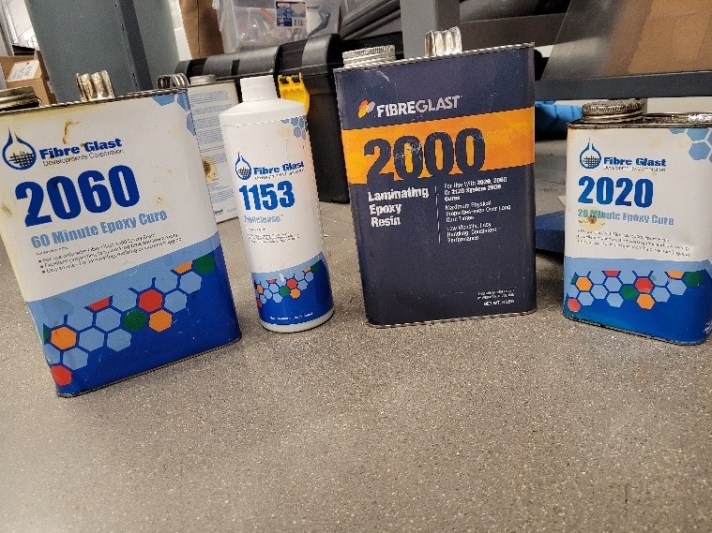
The resin that the club currently uses is the FibreGlast 2000 system. This consists of FibreGlast 2000 Laminating Epoxy Resin, FibreGlast 2020 Epoxy Cure, and FibreGlast 2060 Epoxy Cure. These are shown in Figure 2, along with the 1153 FibRelease. The 2060 and 2020 are typically referred to as hardeners. For large, awkward parts or parts with many plys, use the resin with the 2060 hardener, since that will provide a working time of approximately 60 minutes. For smaller repair jobs or simpler layups, the 2020 hardener can be used, which will have a working time of 20 minutes. The working time of the resin/hardener mixture refers to the amount of time required to complete the layup before the curing reaction begins and it should be under vacuum or some other compression. There are mixing instructions for both of these hardener compounds, given both for volume and weight measurement. Follow the appropriate measurements for mixing the resin and be sure to mix the resin with the hardener only when fully prepared to complete the layup.
The resin and hardener are not safe to handle with bare skin. They also smell nasty and breathing them in is a bad idea, so it is advised to use a mask or respirator. Use caution when handling the resin and hardener. Be aware that the curing reaction is exothermic, so there is a very small chance that carelessness could lead to combustion. This is why we have the safety bucket. Use the safety bucket. Anything that has resin and/or hardener on it that is not going in the bag or a reusable tool goes in the safety bucket. Use care and follow laws regarding the disposal of the safety bucket, as it will be considered hazardous wastewater. For the BIC, this means putting a hazardous waste tag on the bucket and placing it by the overhead doors.
The mixing instructions vary for different resin systems, and resins and hardeners from different systems are not compatible. Be sure to use the resin and hardener from a matching system and always follow the mixing instructions. Once the resin and the hardener are combined, mix thoroughly with a popsicle stick, being sure to scrape the sides. The mixture should end up with approximately the consistency of maple syrup. Be aware that once the resin is mixed, there is a limited working time based on the hardener used, so it may be a good idea to prepare the vacuum bag or the clamping fixture before measuring and mixing the resin (see Step 5).
Step 4 – The Layup
The layup process is conceptually simple. Place a ply on one of the plastic sheets and use a popsicle stick to drizzle resin onto the ply. The resin can also be applied using a paintbrush, but this can increase the chance of FOD (foreign object debris) which can have a negative impact on the strength of the part. Try to use as little resin as possible while still fully saturating the ply. This can be a tricky balance to strike in practice but don’t worry about distributing the resin perfectly the first time. More can always be added and a little can go a long way. Once there is resin on the ply, take a second plastic sheet and place it on top of the ply. Using a clean popsicle stick or another tool (there are carbon tools available in the space that can be used for this and for the actual layup process), spread the resin evenly around the ply. Try to squeeze out any air bubbles and excess resin. By squeezing out air and excess resin, we can make sure that we have a good mass fraction of carbon to resin and ensure a strong, consistent part. Repeat this process on the other plys, so that all the plys for the layup are ready. For this step, it is advised to have multiple people helping to saturate plys so that the layup can be completed within the working time.
Once the plys are ready, bring them to the mold. Peel the top plastic layer off one of the plys, being sure not to distort the weave. Place the ply down on the mold and peel off the remaining plastic layer. Be very careful, as the plastic will pull on the fibers and distort the weave. Try to keep the weave as straight as possible and don’t be afraid to pull the weave back into place. Use a carbon tool to gently poke the carbon fiber into any corners of the mold. The fibers will not want to do this, so be thorough and do not be afraid to apply a little force if necessary. Once again, try not to distort the weave while doing this. Once the ply is entirely in place, fold the excess carbon over the edge of the mold to keep it out of the way. Repeat the process with the other plys. By the end of this process, the mold should have all the plys laid up and some excess over the edges of the mold. If there is a lot of excess, it can be trimmed using scissors (since a razor blade will likely not cut well). Once the plys are in, cut pieces of release film that are large enough to completely wrap the carbon fiber and the molds. The release film will help prevent the resin from bleeding out into the bag and possibly causing a hole as it cures. It will also prevent the bag and breather from getting stuck in the part as it cures, ensuring a cleaner and nicer part. In addition, if a compression mold is being used, it provides yet another physical barrier to prevent damage to the mold. If there isn’t any actual release film available, cut the same shape out of plastic sheeting like the kind used to help spread the resin.
Step 5 – The Vacuum Bag
The vacuum bag is important for the cure cycle because it will provide even, constant compression across the entire part as it cures. This helps provide a nice, consistent composite structure and a decent surface finish, as well as ensuring that the part does not move unexpectedly and cure in a defective manner. However, some parts or molds that can be clamped will not need a vacuum bag since we can achieve a similar effect. Any part that is a flat plate or only needs compression in one direction probably doesn’t need a vacuum bag, provided that clamping and/or weights are available.
The bag will be made using tube bags, which can be found on a roll in the space. Cut the tube bag to a length about 8 inches longer than the part, so that there is plenty of room for sealing the bag and that any resin bleeding won’t reach the edges of the bag. Once the tube is cut, open it by forcing apart the two layers. Take each end of the bag and fold it inside out, forming a sort of sleeve or collar that is about an inch wide. Cut a strip of bag tape that is long enough to wrap around both edges of the bag, so that just over half the perimeter of the collar is covered with the bag tape. Once there is tape on both sides, cut a bed of breather fabric to cover most of the bottom of the bag. This will be the bottom layer and allow air to flow out of the bag much easier. Also prepare long, thin strips of breather that can run the length of the C-channels. This will help to suction the bag into the corners of the channel and prevent bridging. Finally, separate the vacuum valve from the vacuum puck and place the puck inside the bag on a puck plate. The puck plate is just a piece of rigid material (such as a square of balsa or cured carbon fiber), wrapped in breather. This ensures that the vacuum pump is never pulling directly on the bag, and that it is always pulling air through the breather fabric. Since we have a bed of breather, this means that there is constant and consistent suction across the entire bag.
Place the molds wrapped in release film into the bag, being sure to try to keep them away from the sides of the bag. If the mold is roughly a box, wrap the mold in breather as well. For long channels or tight curvatures, thin strips of breather can be run over the part to provide suction in those areas. Make sure that all the breather in the bag is touching the bed so that the air has a consistent pathway to the puck. Regular tape can be used to hold the breather together (for DBF, this means the red or black plastic packing tape mentioned above tape). Other tapes can probably be used, but this is what we have typically gone with before. Once this is done, double-check to make sure that there is a consistent breather trail all across the bag, leading to the puck plate. Also make sure that the puck plate is wrapped in breather, and that the base of the vacuum puck is inside the bag and on the puck plate. Once this is confirmed, seal the bag. To do this, unfold the collars with the bag tape and start to peel off the backing. I find that the best way to do this is to start at one corner of the bag and work my way across that side, peeling off short runs of the bag tape backer and sealing up to that point before continuing. Once the bag is entirely sealed, we will need to cut a hole for the vacuum valve and start to pump air from the bag. To make the cut, pull the bag tight over the vacuum puck. Then, cut a small X in the center of the hole where the valve locks in place. If you want, you can also sprinkle a little isopropanol on the rubber seal to ensure it slides smoothly against the bag. Once the valve is locked, the bag should be completely sealed.
The vacuum pump setup we have at DBF consists of a vacuum pump with a number of fittings on one of the intake valves, including a vacuum pressure gauge. At the end of this is a long pipe that should be pointing straight down, and a quick-connect fitting at the end of the horizontal pipe. The downward pipe is a resin trap intended to catch any resin if it should happen to make it into the vacuum system. Make sure this tube stays pointed downwards. The quick-connect fitting hooks into a vacuum hose in the space, and the other end of the hose has a similar fitting to connect to the vacuum puck on the bag. Make sure the vacuum pump has enough oil in it (max and min fill lines are on the side) and that all the components are in working order. If the system is good to go, connect the ends of the quick-connect hose to the pump and the bag and turn on the pump. The bag will drain slowly at first, but as it approaches negative pressure it will deflate much more quickly. Stop the pump at a point where the bag is starting to get tight but is still able to be moved around a bit (kind of difficult to articulate, but you will know with practice). Try to position that bag such that when the vacuum turns back on, it will create creases in the bag centered on any corners or tight curvatures. To accomplish this, try pinching the bag gently and pulling a crease into position before releasing it into the corner. It is easier to do this with multiple people, since one can run the pump and the others can hold the creases in place. These creases help to prevent bridging in the corners and also help ensure that the bag is tight to the corners. Once these creases are in place, bring the bag to full vacuum. The pump can hold about 30 psi of vacuum, but if there are leaks in the bag it may not get this far. A good test is to bring the bag to full vacuum and then disconnect the pump, so that the bag can be tested. A good rule of thumb is that the bag should only lose about 5 psi over a test period of 5 minutes. However, since we are likely going to have the vacuum on for most of the cure and the parts we are making are not going in an oven, as long as we can disconnect the hose for a little while and still have suction in the bag it will be good enough.
Step 6 – The Cure Cycle
Typically, we will let the resin cure on its own. We also want to keep it under compression for this entire cure, which can be accomplished by a compression mold or by keeping it under vacuum for the entirety of the cure cycle. It is recommended to have the pump under supervision whenever it is running, so making leakproof bags is very important. For a typical vacuum bag, the pump will need to be turned back on every half hour to hour in order to keep the vacuum tight. For the resin described here, the most important part of the cure cycle is the first few hours when the resin is still tacky or flowing. Depending on the hardener and amount of resin used, as well as the size of the part and the temperature of the room, this could be as few as two hours or as many as eight. Typically, the parts will need to cure for at least 24 hours, although the 2060 hardener can take upwards of 36 hours to reach full cure. The more time spent under the vacuum pump, the faster the parts will cure (anecdotally speaking anyway, this may not be accurate). Be sure to keep the vacuum pump oil filled and give the pump breaks when it becomes too hot. The pump currently in the space can run for around 8-10 hours before it begins to get very hot, but always check in just to be sure.
Step 7 – Demolding Parts
Once the cure cycle is complete and the parts are fully cured, they must be removed from the mold. The first step is to get the mold out of the vacuum bag, which can be accomplished quite easily. The bags typically cannot be reused, so cutting the mold out of the bag is the fastest and easiest way to do this. Be sure to set aside and keep the vacuum puck and the puck plate for the next time they are needed. Once the mold is out of the bag, unwrap any breather or release film that is showing. Depending on the geometry of the part, demold can be easy or challenging. Parts such as long channels can be difficult to get started, but once there are gaps between the part and the mold tools can be used to separate the two. Popsicle sticks and bamboo skewers can be useful tools to aid in large demolds. Try to avoid bending parts significantly, as sometimes demold will stress parts in directions that are not designed to withstand loading. There is not a lot of advice that can be given with regards to demold – it takes practice and experience to get a feel for how to separate parts quickly and how much force can be safely applied. These will also vary from part to part, so caution is always advised. Be very careful when demolding parts – carbon fiber is very sharp when cured and will cut deeply if given the chance. Carbon fiber splinters are dangerous because they can be nearly invisible due to their size, and if they are not removed, they will not be broken down by the body. Gloves are advised when doing demold to help provide an extra layer of protection.
Step 8 – Trim and Processing
Once the part is released from the mold, it is likely not in its final form. It will likely need the edges trimmed where excess carbon fiber from the layup process cured, and some parts will need gussets or through holes. When doing any sort of cutting or abrasing of carbon fiber, wear a mask, gloves, and full-coverage clothing. Carbon fiber dust is a carcinogen and a skin irritant that can cause rashes. Always do any cutting or sanding in a ventilated area such as the sanding booth in the BIC or a downdraft table. There is also a clean-room style jumpsuit in the DBF space that is intended for carbon fiber trim. Be sure to wash any clothing that comes into contact with carbon fiber dust as soon as possible.
Carbon fiber trim can be accomplished with a variety of tools, but the easiest for the club’s purpose is the Dremel tool. The cutting wheels designed for metal work well on carbon fiber when used at a relatively high speed, and the carbon fiber can also be sanded using regular sandpaper. The part can be marked prior to cutting using the white paint pens in the space, although silver permanent marker and white crayon work as well. When cutting using the Dremel tool, it works best to take multiple light passes rather than trying to make a deep cut right off the bat. Be sure to try and keep the Dremel out of the way of the carbon dust, as it can suck the dust through the tool’s intake and cause it to overheat and burn out. Carbon can also be cut using hacksaw blades and drilled into with standard drill bits, but the same precautions must be taken with regard to dust exposure. In addition, when cutting, the carbon may splinter, so be aware of any edges of the part and be sure to sand thoroughly.
Step 9 – Bonding Parts (Optional)
For some parts, the geometry is too complex to be made from a single mold. In this case, cured carbon fiber parts can be bonded together to create the geometry required. The bonding process is essentially another layup and can be done using much of the information relayed above. Depending on the orientation of the bond, it may not be necessary to create a full vacuum bag if compression can be created another way.
Before bonding two parts, it is important to make sure that the surfaces are clean and prepared for optimal bonding. To do this, lightly sand the surfaces that will be bonded together and then clean them using isopropanol, similar to how the molds were cleaned in step one. Once the parts are ready, mix a small amount of resin and hardener and apply it to the bonding surfaces. For some parts, it may be advantageous to use a reinforcing ply as well, which can be saturated like in a normal layup and placed along the bond. The resin will once again need time to fully cure, so be sure that multiple cure cycles are accounted for if this step is needed.
