Intro
The goal of this guide is to provide a straightforward, formulaic method for determining the optimal airfoil choice for a given aircraft. This is a process beginning with the aircraft’s mean aerodynamic chord, wingspan, aircraft cruise speed, and required wing thickness. The end result is an airfoil profile that can be manufactured. This was originally written for the DBF competition team.
Airfoil Basics
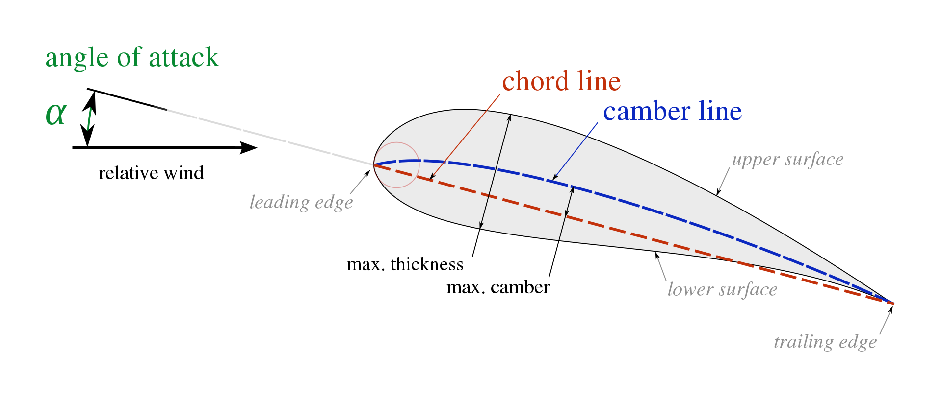
Airfoils are special shapes that provide lift when air flows over them. They create the lifting force that keeps airplanes aloft. They are also important to the design of the tail and control surfaces. The design of an airfoil is, however, a comparatively small component of the overall vehicle performance, and quite frankly a non-essential step in the process. Choosing a generic airfoil or even a flat plate will still allow the aircraft to fly, as long as the rest of the aircraft was designed and built appropriately. Regardless, the appropriate airfoil will provide significant performance gains. There are two key dimensions to an airfoil, the thickness, and the chord length. These combined represent the overall size of the airfoil, which is particularly useful when the interior shape of the wing is important.
The airfoil shape is also important for the internal wing structure. For example, the 2022-23 competition included a wing-loading mission, where the stronger wings scored better. As such, a taller wing provides a substantially more structural design from a statics perspective, which is part of what led my team to our prototype choices. Most model aircraft have a single airfoil shape that is repeated down the length of the wing, but more complex designs will have variable sizes or even different shapes along the length of the wing. Birds, for instance, have an extremely dynamic “airfoil” that changes along the length of their wings. For the sake of manufacturing and calculation complexity, most model aircraft and design processes do not address variable airfoil designs. As such, the process that I developed here will only provide a singular airfoil choice.
Airfoil Categories
There are several different categories of airfoil profiles, with a range of complexity and performance characteristics. The conventional shapes and characteristics are detailed by these figures from Joyplanes (https://joyplanes.com/en/selection-of-airfoil-model-airplanes/). Please visit their site so they get traffic credit for their work.
Conventional Hobby Processes
Airfoil choices are a comparatively small factor in overall performance, so optimizing them is often greatly simplified at the hobby scale. Most model aircraft manufacturing processes also limit the detail a given profile choice can contain. For example, folding foamboard at a small scale will be heavily constrained to simple curves and blocky trailing edges. Balsa models and hotwire designs are much easier to manufacture profiles with, allowing hobbyists to recreate curvature much more accurately to their design. The approach to airfoil choice is then dependent on the manufacturing processes and the intended behavior of the aircraft. As seen in the airfoil categories, a simple DIY aircraft would likely utilize a Flat, KF, or Flat-Bottom airfoil purely to reduce manufacturing and repair complexity. On the other hand, a $10,000 RC jet has likely been thoroughly evaluated on an aerodynamic level and built with a variable-profile NACA airfoil or based on a real aircraft design that was carefully selected to minimize drag and stall tendencies. By nature, there is a huge range in the complexity that hobby projects can take. Most hobbyists prefer to copy popular airfoils since they have well-established tendencies and, “the truth is that almost nobody will know how to select an airfoil based on airfoil data, because it’s not necessary, it’s not worth the trouble” (JoyPlanes). Typically a plane will be compared to similar existing designs and copy their choices, using standards like the Clark-Y airfoil we chose for our prototype. This is the hobby methodology, to copy a similar vehicle or select from a vehicle class standard.
Available Data
Airfoil performance is very complicated to mathematically determine from geometry alone, so most airfoils are tested in wind tunnels under a variety of conditions to measure their performance across a range of speed and pressures. If this were a more extensive project, the airfoils would be designed from scratch, optimized entirely to the missions. This test data is readily available at airfoiltools.com, (and other places, but they are much harder to search through), and is normalized by Reynolds number, Cm, and Cl/Cd values. The Reynolds number represents the qualities of the airflow, Cm is the moment the airfoil produces, and Cl and Cd represent the lift and drag, respectively. The relationships between these values and alpha, or the angle of attack, are plotted in the airfoiltools.com database such that inspecting a particular airfoil will reveal key dynamics. These dynamics can then be used in the design process to optimize the vehicle.
General Process
To select well-optimized airfoils we can follow a simple design process. Note that all calculations will be done at the end. The methodology is shown in the flowchart below and is explained in the following text.
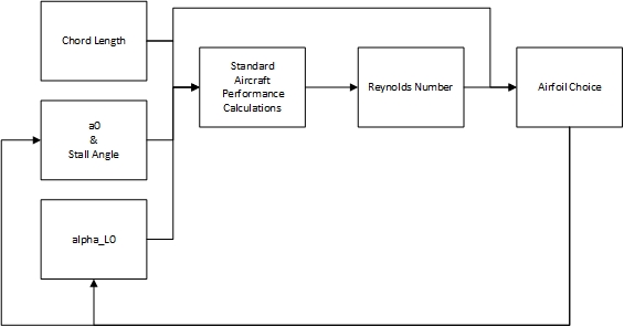
The process begins with the conventional simplification of an airfoil into a Cl/alpha ratio, which is what is taught in the Intro to Aero and Aircraft Design classes. This gives us a value, a0, that represents the airfoil performance. This begins with a standard value, a0 = 10/deg. This initial guess is accompanied by a stall angle of alpha = 10 deg. that was likewise determined from average airfoil performance and provides a usable baseline.
The aircraft is then designed with those values, giving us the size and speed of the vehicle. From these, and more specifically the chord length and cruise velocity, we can generate a Reynolds number for the vehicle. We can also estimate from the missions a few key parameters, such as which type of wing will be needed. For example, this year’s plane (2022-2023) is designed for both speed and carrying capacity. Without the need for acrobatics, we should be looking for a semi-symmetric airfoil. If the missions did not require speed, we would choose an under-cambered profile. On the other hand, if we did not need to carry heavy weights we would favor a more symmetric airfoil for less drag.
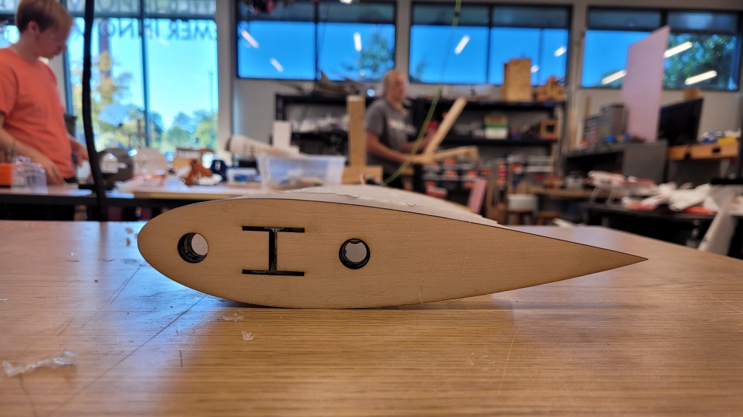
This plane example also calls for a thick wing to support a large spar, so we need to choose an airfoil that is relatively thick. This is where the mission factors come into play, and every choice has some tradeoffs. For manufacturing reasons, we chose a minimum thickness that the airfoil needed to be (relative to the chord length) to fit a standard size of aluminum I-beam.
Finding the right airfoil
With the constraints from the previous section, the Reynolds number, and the knowledge that we wanted a semi-symmetric airfoil, we can find the optimal airfoil. Using airfoiltools.com, we can search for the best Cl/Cd under our filters, Reynolds = 580,0000 and max thickness = 12%.
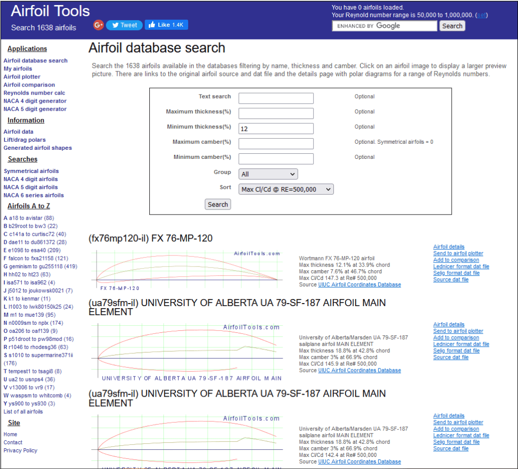
Studying the results, we can see that the first airfoil, the FX 76-MP-120 – Wortmann FX 76-MP-120, matches our criterion. It is a semi-symmetric airfoil, and a study of the plots reveals that it has relatively stable characteristics down to 9 m/s (20 mph) which is below our anticipated stall speed. Stalls are a crucial, yet often ignored, part of aircraft design. They occur when, as the angle of attack is increasing, the airfoil suddenly transitions from producing high lift to producing almost no lift. Inspecting the top of the Cl vs alpha curve, we can see that this transition is gentle, not sharp, which is good for our pilot.
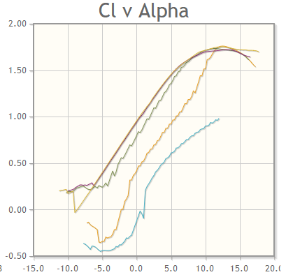
This gentle transition means that when the aircraft approaches a stall the pilot will get a bit of warning, allowing them to maneuver the vehicle out of the stall before they lose control. In choosing an airfoil, it is wise to select airfoils with a gentle stall transition, allowing for more controllable turns, takeoff, and landing.
The next two options demonstrate an incomplete outer perimeter and do not provide stable lift characteristics.
Comparing the next couple of airfoils using the comparison tool, we can see that the one we chose provides the best ratios of lift to drag and lift to alpha, only performing worse when the angle of attack is negative (note that for this vehicle we do not care about acrobatic maneuvering. Note that the purple line is our currently selected airfoil at Reynolds = 500,000.
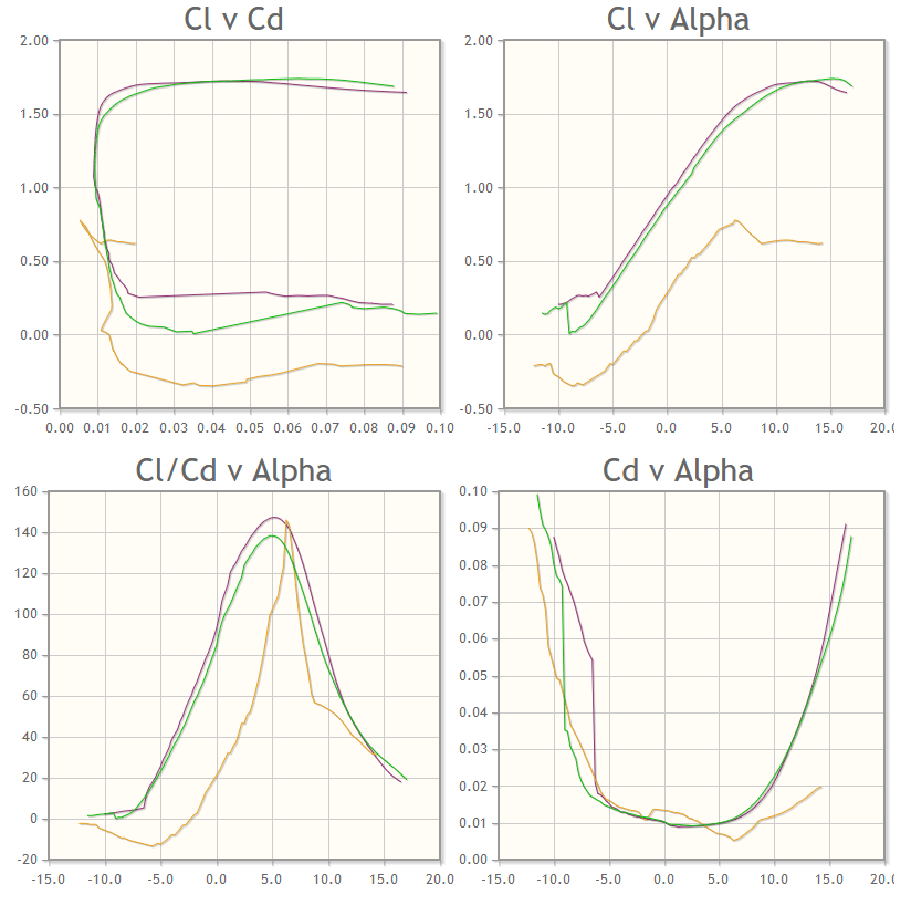
This indicates we have chosen the most optimal airfoil for our parameters since the results were also sorted by the performance at our specified Reynold value. Note that in this scenario our a0 and stall angle remained the same. The alpha_L0 did change, so we can re-run the vehicle performance calculations. This gives us very similar results, so we can end our loop. The Cl and Cd of the airfoil cannot be directly compared to our vehicle model, since the airfoil data does not account for a finite, tapered, or swept wing. As such, the full benefit of the airfoil choice does not show up before the vehicle is tested. Note that the tail surfaces follow this same process with symmetric airfoils.
Exporting the Airfoil
Now that we have chosen an airfoil to use, we can use the website’s built-in export control to generate the wing we want. Select the airfoil plotter, and it will bring up a menu of different export options. To learn how to import the design into Solidworks, follow this tutorial https://www.youtube.com/watch?v=aT9z-D_dwU4. Make sure to double-check your scaling and ensure the wing set angle is correct with respect to the full model.
